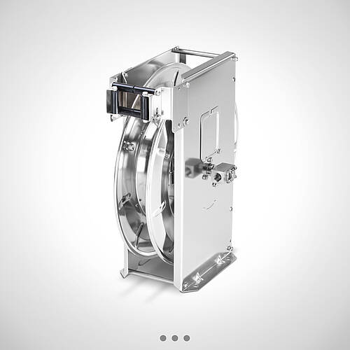
Examples of hose reel installations
Suitable mounting for the specific installation situation
Hose reels must not only integrate reliably into the workspace, but also suit the existing wall, ceiling and room layout. In addition to standard installation without a bracket, various optional mounting options are available for this purpose. These allow the hose reel to be positioned as required, take account of structural conditions and facilitate clear hose routing.
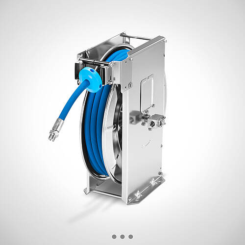
The following installation examples show how automatic hose reels can be mounted depending on the installation location, hose outlet and desired working area.
Angle brackets for fixed wall mounting –
positions 1 to 3
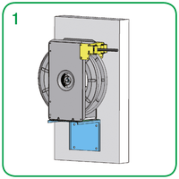
The angle brackets are designed for fixed wall mounting and are suitable wherever the hose reel needs to be aligned parallel to or at right angles to the wall.
Position 1 shows the angle bracket for fixed wall mounting parallel to the wall. This version is suitable for installation situations where the hose reel is to be positioned close to the wall and arranged in a parallel configuration.
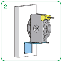
Position 2 shows the angle bracket for fixed wall mounting at right angles to the wall. This allows the hose reel to be positioned to the side of the wall, facing into the room.
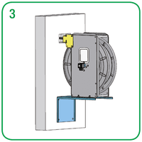
Position 3 adds a wall feed-through to this variant. It is ideal when the hose is to be routed through a wall and the reel is mounted on the opposite or adjacent side.
The fixed angle brackets provide a defined mounting position and make it easier to adapt the hose outlet to the specific room layout.
Bracket for fixed wall and ceiling mounting –
Positions 4 to 6
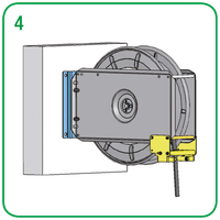
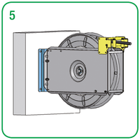
The bracket for fixed wall and ceiling mounting allows installation on a wall or ceiling. Depending on the version, the hose can be routed downwards or forwards.
Position 4 shows wall mounting with the hose outlet facing downwards. This variant is suitable for work areas where the hose is to be positioned directly below the reel.
Position 5 shows wall mounting with the hose outlet facing forwards. This is suitable when the hose needs to be routed specifically into the room.
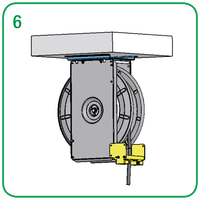
Position 6 shows ceiling mounting. This version may be useful if wall space needs to be kept clear or if the hose is to be routed into the work area from above.
The wall and ceiling brackets expand the options for positioning the hose reel. This allows the installation to be better adapted to existing surfaces, walkways and workflows.
Wall-mounted swivel bracket with 180° swivel range –
Positions 7 and 8
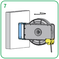
The wall-mounted swivel bracket allows a swivel range of 180°. This enables the hose reel to be moved and aligned according to the direction of work.
Position 7 shows the wall-mounted swivel bracket with the hose outlet facing downwards.
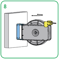
Position 8 shows the wall-mounted swivel bracket with the hose outlet facing forwards.
The swivel range allows for flexible use in different working positions. At the same time, when not in use, the hose reel can be swivelled closer to the wall, keeping the area in front of it clear.
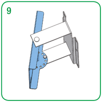
Swivel brackets with seven locking positions –
Position 9
The WSK-T 40/1 and WSK-T 40/2 swivel brackets can each be locked into seven positions. This means that the hose reel can not only be swivelled, but also fixed in a specific working position.
This solution is particularly suitable when serving recurring work areas and a fixed orientation of the hose is required. The locking mechanism ensures reproducible positioning and supports orderly hose routing.
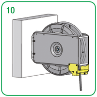
Standard mounting without bracket –
Position 10
With standard mounting, the hose reel is fitted directly without an additional bracket. This design offers a compact solution where the existing mounting surface, the desired hose direction and the working area are already aligned with one another.
Compared with the optional brackets, direct mounting offers fewer options for spatial alignment. However, it reduces the installation effort and is suitable for clearly defined installation scenarios.
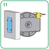
Backplate for lightweight walls –
Position 11
With lightweight walls, a backing plate is particularly important for secure installation. It distributes the forces acting on the unit over a larger area and ensures the hose reel is securely fixed to the wall structure.
The backing plate should be taken into account at the planning stage so that the wall structure, fixing methods and the load from the hose reel are all coordinated.
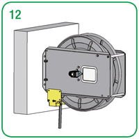
Hose routing close to the wall –
Position 12
Position 12 illustrates the option of routing the hose close to the wall, rather than allowing it to exit at the front. This variant may be useful if the hose reel is to be positioned as close to the wall as possible, or if the area in front of the unit is to remain clear.
This allows the hose routing to be adapted to confined installation spaces and to the desired path within the working area.